


Shop Drawings – Understanding Their Role in Accurate Construction and Fabrication
Shop drawings are the critical transition from design intent to information clear enough for coordinated fabrication, manufacturing, installation, construction, inspection, acceptance and operation.

In technical projects, many failures do not arise from the absence of drawings, but from drawings that are not sufficiently clear for execution. Unconfirmed dimensions, uncoordinated elevations, incomplete material information, unresolved interfaces or details that do not reflect fabrication and installation constraints can cause rework, delay, waste and contractual disputes.
Shop drawings should therefore never be treated as a simple redrawing of the design documents. Their real value is to convert design requirements into controlled, executable technical information.
1. What Is a Shop Drawing?
A shop drawing is a detailed execution drawing prepared on the basis of approved design documents, specifications, technical standards, equipment data, contractual requirements and actual site conditions. It is used directly for:
A good shop drawing must answer:
- What is to be executed, where, and to what dimensions?
- Which materials, components and equipment are required?
- How are the details, connections, tolerances, levels and installation sequence defined?
- Are there conflicts with architecture, structure, MEP, process systems or maintenance clearances?
- Who prepared, checked and approved the drawing, and which revision is valid?
2. Design Drawings, Shop Drawings and As-Built Drawings

| Criterion | Design Drawing | Shop Drawing | As-Built Drawing |
|---|---|---|---|
| Purpose | Defines design intent, performance and technical requirements. | Converts design requirements into information for fabrication, installation and construction. | Records the actual completed condition. |
| Timing | Prepared before execution. | Prepared before and during construction planning. | Prepared after the work is completed and verified. |
| Prepared by | Designer or design consultant. | Main contractor, subcontractor, fabricator or supplier. | Contractor, based on verified field conditions. |
| Main content | Overall geometry, performance, loads, materials and applicable standards. | Detailed dimensions, levels, connections, openings, component codes and installation information. | Approved changes, actual locations and final dimensions. |
| Use | Design and contractual basis. | Direct basis for execution and control. | Basis for operation, maintenance, modification and traceability. |
3. Why Shop Drawings Matter
Reduce errors and rework
Clear information limits assumptions, incorrect installation, cutting, demolition and repeated work.
Coordinate disciplines
Architecture, structure, MEP, process equipment and maintenance zones are checked on a common basis.
Standardize fabrication
Component codes, connection details, tolerances, materials and fabrication sequences are consistently defined.
Control quality
QA/QC, consultants and owners have a clear basis for inspection, acceptance and technical traceability.
Support schedule control
Drawings can be released by zone, work package and construction priority to match the actual program.
Reduce contractual risk
Revision records, comments and approvals provide a traceable history of technical decisions.
4. Where Are Shop Drawings Used?
The use of shop drawings extends far beyond building construction. Any industry that converts design information into a physical product or installed system requires detailed execution documentation.
Construction and infrastructure
- Reinforced concrete, rebar and formwork
- Structural steel, bridges, roads and utilities
- Architecture, façades, glazing and finishes
MEP and building systems
- Electrical, HVAC, plumbing and fire protection
- Cable trays, ductwork and piping
- BMS, ELV, compressed air and process systems
Mechanical and fabrication
- Machinery, tanks, silos and piping
- Welded details, machining and assembly
- Supports, platforms and industrial stairs
Factories and industry
- Production lines and utility systems
- Cement, energy and environmental systems
- Warehousing, food, chemical and plant infrastructure

5. What Should a Professional Shop Drawing Set Include?
| Information Group | Required Content | Risk if Missing |
|---|---|---|
| Document control | Project, zone, drawing number, revision, issue date and approval status. | Wrong revision, poor traceability and unclear responsibility. |
| Design basis | Referenced drawings, specifications, standards, RFIs and approved changes. | Execution inconsistent with the governing documents. |
| Geometry | Plans, elevations, sections, details, coordinates, levels and dimensions. | Incorrect position, dimensional errors, clashes or installation failure. |
| Materials and equipment | Type, grade, size, code, standard and technical data. | Incorrect procurement, fabrication or incompatibility. |
| Connections and construction details | Bolts, welds, anchors, supports, sleeves, inserts, accessories and tolerances. | Safety, quality and rework risks. |
| Coordination | Interfaces with architecture, structure, MEP, equipment and maintenance zones. | Spatial conflicts and restricted operation or maintenance. |
| Execution notes | Sequence, inspection requirements, hold points, testing and acceptance criteria. | Inconsistent execution and insufficient acceptance basis. |
6. BIM, Clash Detection and Shop Drawings
BIM brings information from multiple disciplines into a coordinated environment. Tools such as Revit, Tekla, Navisworks, AutoCAD, Civil 3D, Plant 3D and common data environments can support modelling, clash detection, revision control and drawing extraction.
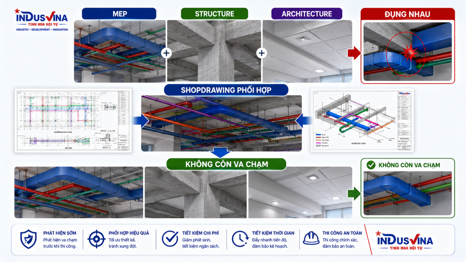
Clash detection is more than checking physical intersections
- Hard clash: two objects occupy the same space.
- Soft clash: insufficient clearance for installation, insulation, access or maintenance.
- Workflow clash: the construction sequence is impractical or one activity blocks another.
- Data clash: inconsistent codes, specifications, materials or equipment data.
BIM does not replace professional responsibility. A model is only valuable when its input data is reliable, checking rules are clear and the coordinated outcome is issued through a controlled drawing workflow.
7. Shop Drawing Preparation, Review and Approval Workflow
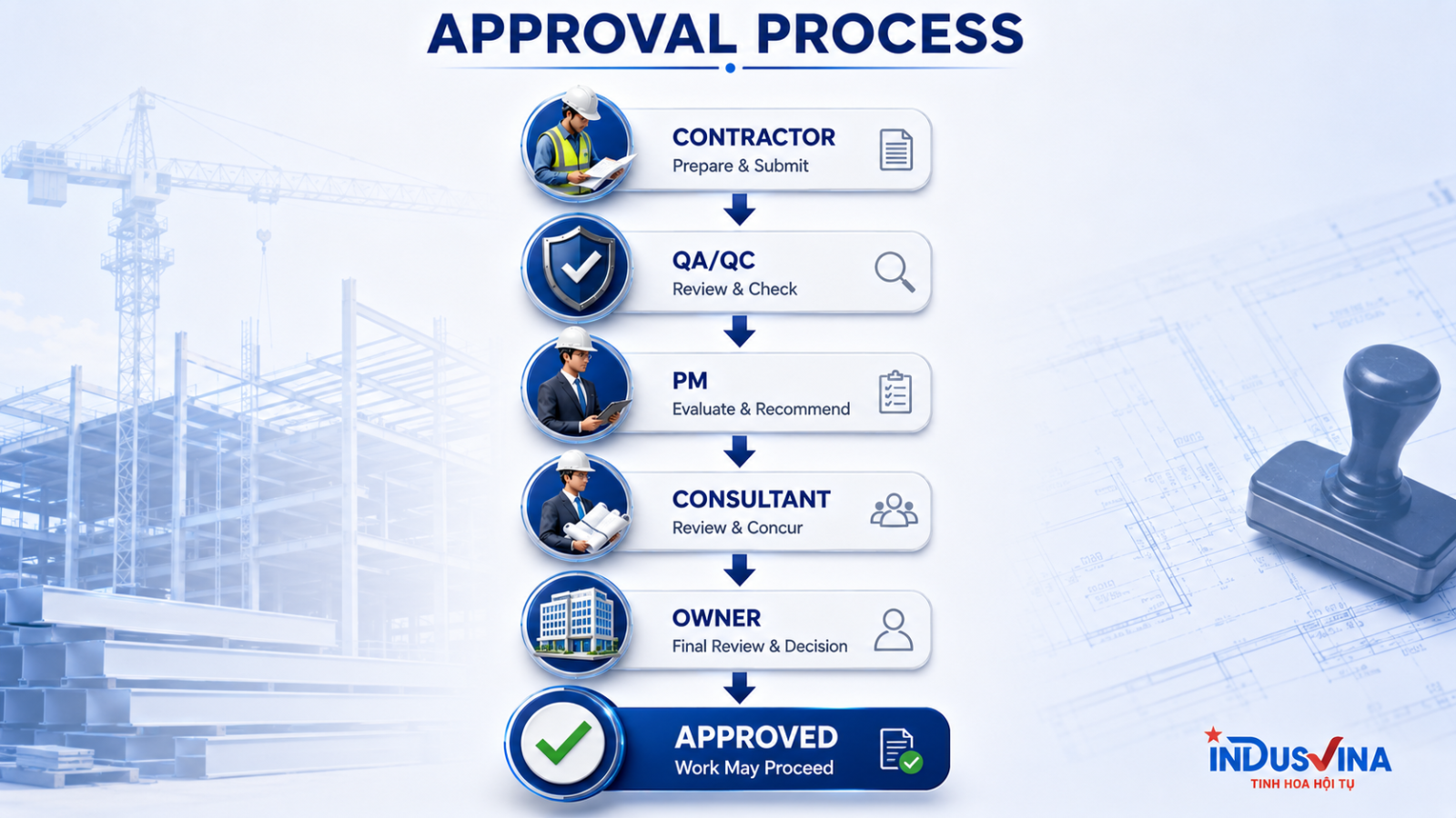
Review input documents
Collect the design, specifications, equipment data, BOQ, standards, RFIs and site information.
Plan the deliverables
Divide the work by zone, system, fabrication package, priority and issue date.
Develop the drawings
Show geometry, materials, connections, levels, component codes and installation information.
Coordinate all disciplines
Check architecture, structure, MEP, process systems, operation and maintenance requirements.
Perform internal review
Lead engineers, QA/QC, project management and relevant departments review the drawings before submission.
Submit and address comments
Respond to each review comment, update the revision and formally clarify every change.
Issue for construction or fabrication
Only drawings with the correct status, valid revision and formal authorization may be used.
Control changes and update as-built records
Withdraw superseded drawings, record field changes and update the final documentation.
8. Pre-Submission Shop Drawing Checklist
9. Practical Example: Coordinating MEP Shop Drawings
A technical ceiling zone may contain ductwork, fire protection piping, water pipes, cable trays, lighting, structural beams and suspended equipment. When each discipline works independently, conflicts are often discovered only after construction has begun.
Before coordination
- Ductwork conflicts with beams
- Cable trays cross sprinkler coverage zones
- Insufficient ceiling clearance
- No access for maintenance
After coordination
- Services are layered by priority
- Main routes and crossings are fixed
- Openings, supports and access zones are defined
- A coordinated drawing is issued

10. Common Mistakes to Avoid
- Copying design drawings without adding execution information.
- Producing visually attractive but incomplete drawings that lack dimensions, levels, materials or connections.
- Ignoring site surveys or relying on inaccurate base information.
- Failing to coordinate disciplines, so each package works independently but the overall system cannot be installed.
- Poor revision control, allowing multiple versions to circulate at the same time.
- Starting work before approval.
- Failing to record changes in the as-built documentation.
- Ignoring maintainability, so equipment can be installed but not safely accessed or removed.
11. Standards and Reference Principles
Depending on the discipline, shop drawings may refer to TCVN, QCVN, project standards, ASTM, ACI, AISC, AWS, ASME, API, BS, Eurocodes, JIS, IEC, ISO, NFPA, SMACNA, ASHRAE or manufacturer requirements.
12. Shop Drawings in the Project Life Cycle

Well-managed shop drawing data supports inspection, as-built documentation, O&M handover, asset management, maintenance, modification and future expansion of the facility or production line.

13. Conclusion
Shop drawings are where design capability, construction experience, fabrication knowledge and document-control discipline come together. A good drawing must be coordinated, fabricable, buildable, installable, inspectable, acceptable and maintainable.
Proper investment in shop drawings reduces errors and rework, improves schedule predictability and raises the quality of the final product.
Related Articles
FAQ – Frequently Asked Questions About Shop Drawings
What is a shop drawing?
A shop drawing is a detailed execution drawing developed from design documents and technical data for fabrication, construction, installation, inspection and acceptance.
Is a shop drawing the same as a design drawing?
No. Design drawings define intent and requirements. Shop drawings explain how those requirements will be executed while remaining compliant with the approved design.
Does a shop drawing replace an as-built drawing?
No. Shop drawings are used before and during execution. As-built drawings record the verified final condition after completion.
Who prepares and approves shop drawings?
They are commonly prepared by contractors, subcontractors, fabricators or suppliers. The review and approval process depends on the contract, project organization and assigned responsibilities.
Does BIM replace shop drawings?
Not entirely. BIM supports modelling, coordination and clash detection, while shop drawings remain controlled documents for fabrication, construction, installation and acceptance.
Connect with INDUSVINA
INDUSVINA supports clients and partners with site surveys, technical coordination, shop drawing development, MEP construction, civil works, mechanical fabrication, plant upgrades and MRO maintenance services.


