


Steel Structures & Pre-Engineered Buildings – Design, Fabrication, Erection and Technical Standards
A steel structure must not only contain enough steel – it must be correct from design to operation
Steel structures and Pre-Engineered Buildings are suitable solutions for factories, warehouses, logistics centres, distribution facilities and industrial buildings requiring large clear spans, rapid construction, future expansion and document-based quality control.
However, the advantages of steel can only be realised when the entire project chain is controlled: survey, design, shop drawings, material selection, fabrication, welding, surface treatment, transportation, erection, inspection, handover and life-cycle maintenance.
1. What are steel structures and Pre-Engineered Buildings?
A steel structure is a load-bearing system comprising columns, beams, rafters, bracing members, connection plates, bolts and other steel components that transfer structural loads to the foundation. It may be used independently or combined with reinforced concrete, wall systems, composite floors and MEP systems.
A Pre-Engineered Building – PEB is a building in which the main structural members are analysed, designed and fabricated in a controlled factory environment, then transported to the construction site for erection in accordance with approved documents.
Conventional steel structures
- May use hot-rolled sections or built-up steel members.
- Suitable for industrial, civil and specialised infrastructure projects.
- Flexible design based on structural loading and architectural requirements.
- May be integrated with composite floors, concrete systems and complex bracing.
Pre-Engineered Buildings
- Member sections are optimised according to forces along the frame.
- Industrial fabrication and modular erection enable faster delivery.
- Suitable for factories, warehouses and large-span buildings.
- Convenient for future expansion or operational changes.
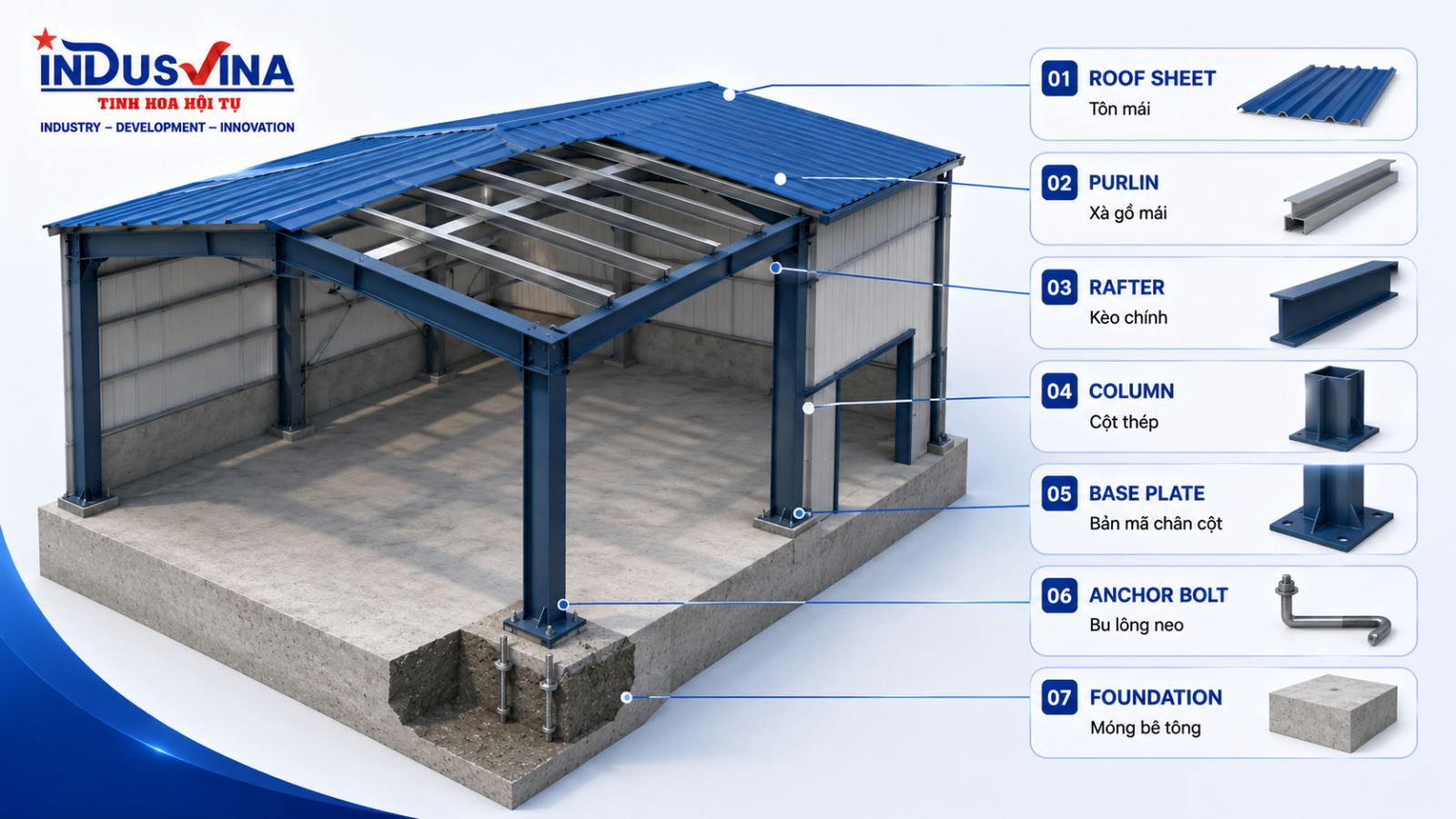
2. Technical components of a Pre-Engineered Building
2.1. Primary structural system
- Built-up or hot-rolled I/H steel columns.
- Roof rafters, main beams and connecting beams.
- Crane runway beams where overhead cranes are installed.
- Connection plates, stiffeners and end-plate connections.
2.2. Secondary structural system
- C- or Z-section roof and wall purlins.
- Roof, wall and end-wall bracing systems.
- Sag rods, anti-roll members and stability components.
- Secondary frames for doors, canopies and equipment.
2.3. Cladding system
- Roof sheets, wall sheets or insulated panels.
- Gutters, downpipes and roof-edge details.
- Skylights, ventilation systems and louvers.
- Flashing and waterproofing details.
2.4. Connection system
- Anchor bolts connecting columns to foundations.
- High-strength bolts at structural frame joints.
- Factory or site welding where required.
- End plates, splice plates and column base plates.
2.5. Foundation system
- Pad, strip or piled foundations.
- Reinforced-concrete pedestals and steel base plates.
- Anchor bolts, non-shrink grout and levelling plates.
- Foundation beams, tie beams and industrial floors.
2.6. Related process systems
- Overhead cranes and crane runway rails.
- Piping, cable trays and MEP equipment.
- Machinery supports and suspended loads.
- Lightning protection and grounding systems.
3. Common types of steel buildings
Manufacturing facilities
Large-span spaces integrating overhead cranes, process equipment, ventilation, lighting and mechanical and electrical systems.
Logistics warehouses
Designed to optimise storage space, forklift circulation, clear height, fire safety and future expansion.
Crane buildings
Require careful control of dynamic loading, lateral forces, crane-beam deflection, rails, connections and crane duty class.
Multi-span steel buildings
Use multiple column lines or continuous frames to accommodate wide production areas and large building footprints.
Canopies and auxiliary structures
Canopies, platforms, stairs, walkways, equipment supports, pipe racks and technical buildings.
Renovation and expansion projects
Existing-frame strengthening, roof raising, span extensions, crane additions and changes in operating loads or building use.
4. Why are steel structures widely used?
| Benefit | Technical meaning | Value for the owner |
|---|---|---|
| Large clear spans | Steel has a high strength-to-weight ratio and is suitable for spaces with fewer internal columns. | Improves production-line layout, logistics flow and equipment arrangement. |
| Rapid construction | Factory fabrication may proceed in parallel with foundation construction. | Reduces the time required to place the building into operation. |
| Quality control | Materials, dimensions, welding and coating can be inspected at each stage. | Reduces rework, disputes and acceptance risks. |
| Lower self-weight | Steel systems often weigh less than many conventional structural alternatives. | May optimise foundation dimensions and reduce ground pressure. |
| Future expansion | Steel frames are convenient to extend, raise or adapt to operational changes. | Supports the long-term development of factories and warehouses. |
| Reuse and recycling | Many members may be dismantled, replaced, reused or recycled. | Supports more efficient use of resources. |
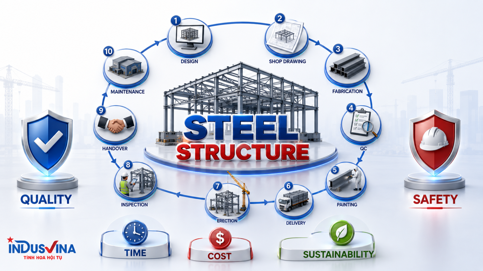
5. Steel structure design, fabrication and erection process
Survey and requirement definition
Clarify the layout, building use, span, height, crane requirements, geotechnical conditions, production technology and expansion plans.
Concept design
Establish the structural arrangement, frame spacing, bracing system, materials, loads and cladding concept.
Structural design
Analyse loads, internal forces and global stability, verify members and design structural connections.
Shop drawings
Develop fabrication dimensions, connection plates, bolt holes, weld symbols, member marks and tolerances.
Factory fabrication
Cutting, drilling, fit-up, welding, straightening, dimensional inspection and member completion.
Surface treatment
Cleaning, protective coating, finishing paint or galvanising, depending on the service environment and project requirements.
Transportation and site delivery
Divide delivery lots, protect coatings, plan loading sequences and organise unloading and storage at the site.
Erection
Install columns, rafters, bracing, purlins and cladding while controlling temporary stability, grid lines, levels and connections.
Inspection and acceptance
Inspect geometry, bolts, welds, protective coatings, cladding systems and quality records.
Handover and maintenance
Complete as-built documentation, acceptance records, operational guidance and periodic inspection plans.

6. Shop drawings – the bridge between engineering and production
Shop drawings are the documents directly used for fabrication and erection. A small drawing error may result in incorrect bolt holes, incorrect connection plates, incorrect member lengths or members that cannot be assembled on site.
Information to be shown
- Member identification and erection location.
- Overall dimensions and fabrication dimensions.
- Connection plates, stiffeners and bolt holes.
- Weld symbols, lengths and weld sizes.
- Material grades, bolt classes and surface requirements.
- Fabrication and erection tolerances.
Interfaces to be coordinated
- Architecture, reinforced-concrete structures and floor levels.
- Anchor bolts and foundation pedestals.
- Overhead cranes, process equipment and suspended loads.
- MEP systems, piping, cable trays and fire-protection systems.
- Doors, rolling shutters, canopies and ventilation systems.
- Transportation, lifting and erection methods.
7. Factory fabrication of steel structures
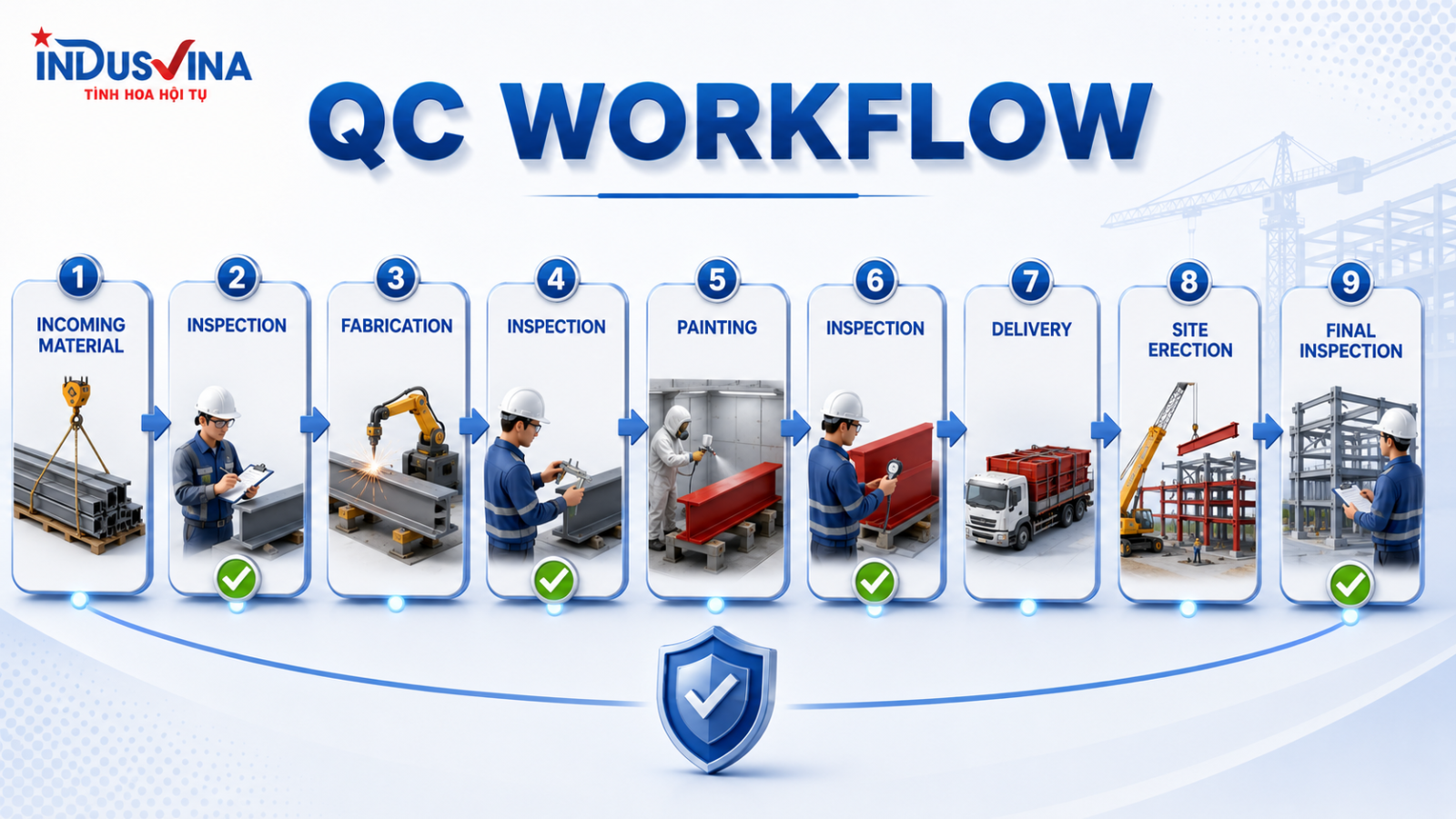
Material inspection
Verify section size, steel grade, thickness, material certificates, batch identification and surface condition before production.
Cutting and drilling
Control dimensions, cut quality, hole positions, squareness and prepared-edge quality.
Member fit-up
Check centrelines, flange and web dimensions, straightness, squareness and connection-plate positions before welding.
Welding
Apply suitable welding procedures and control consumables, parameters, welding sequence and heat-related distortion.
Straightening
Inspect bow, twist and welding deformation and correct them through controlled methods.
Final fabrication inspection
Verify dimensions, quantities, member marks, weld quality and surface condition before coating.
8. Welding and bolted-connection control
Welding control
- Approve welding procedures in accordance with project requirements.
- Confirm welder qualifications and approved welding ranges.
- Inspect joint preparation, root gaps, fit-up and preheat where required.
- Perform visual inspection and NDT at the specified level.
- Repair defects through an approved repair procedure.
- Issue reports and maintain weld-location traceability.
Bolted-connection control
- Correct bolt type, diameter, length and strength class.
- Correct combination of bolt, nut and washer.
- Faying surfaces suitable for the connection design.
- Initial tightening and final tightening in the correct sequence.
- Torque or tension control in accordance with project requirements.
- Marking and inspection records for completed connections.
9. Protective coating, galvanising and life-cycle cost
The surface-protection system must be selected according to the operating environment, required service life, maintenance accessibility and application conditions. The decision should not be based solely on the initial coating price.
Surface preparation
- Remove oil, grease, rust, weld slag and contaminants.
- Use mechanical cleaning or abrasive blasting as required.
- Inspect surface cleanliness and profile.
- Control the time between cleaning and coating.
Multi-coat systems
- Anti-corrosion primer.
- Intermediate coat for additional protective thickness.
- Finish coat for weather resistance and colour.
- Control individual and total dry-film thickness.
Galvanising
- Suitable for external members and smaller components.
- Bath dimensions and venting holes must be considered.
- Thermal distortion must be addressed during member design.
- Damaged galvanised areas must be repaired where necessary.
| Typical environment | Characteristics | General solution direction |
|---|---|---|
| Dry internal environment | Low humidity and low corrosive exposure. | Basic coating system according to appearance and service-life requirements. |
| Industrial environment | Humidity, dust and industrial contaminants may be present. | Higher surface-preparation level and greater coating thickness. |
| External or coastal environment | High humidity, salt exposure and severe weathering. | High-performance coating or galvanising, depending on the member. |
| Chemical environment | Exposure to specific chemical vapours, gases or substances. | Separate assessment according to chemicals and operating conditions. |
10. QC/QA and Hold Points in steel structure projects
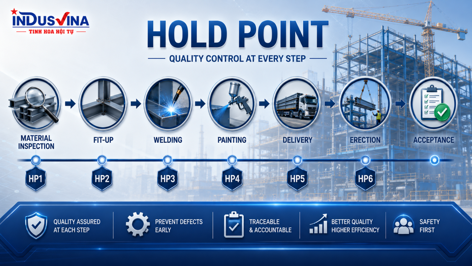
Quality is not inspected only at the end of the work. The QC/QA system must define inspection points, witness points, hold points and approval responsibilities before the next activity begins.
| Stage | Main control point | Records or evidence |
|---|---|---|
| Design | Standards, loads, analytical model, connections and technical interfaces. | Design basis, calculations, drawing register and RFIs. |
| Shop drawings | Dimensions, plates, bolt holes, weld symbols and member identification. | Approved drawings, transmittals and revision register. |
| Materials | Dimensions, grade, certification and traceability. | MTCs, CO/CQ and incoming-material inspection records. |
| Fit-up | Assembly, root gaps, dimensions, centrelines and plate positions. | Fit-up inspection reports. |
| Welding | Procedures, personnel, visual quality and non-destructive testing. | WPS/PQR/WPQ, visual reports and NDT reports. |
| Coating or galvanising | Surface preparation, environmental conditions and coating thickness. | Surface-preparation and DFT reports. |
| Erection | Grid lines, levels, verticality, temporary bracing and bolted connections. | Survey reports, torque records and erection checklists. |
| Handover | As-built documentation, outstanding items, quality records and maintenance guidance. | As-built drawings, punch lists and handover dossier. |
11. Steel erection at the construction site
Preparation activities
- Inspect the work area, access roads and crane positions.
- Verify grid lines, elevations and anchor bolts.
- Prepare the erection sequence and temporary-stability plan.
- Determine crane capacity, radius and configuration.
- Arrange storage zones and ground-assembly areas.
Erection control
- Erect columns and stabilise them with temporary bracing.
- Install rafters in sections or preassemble them at ground level.
- Install sufficient bracing before releasing lifting equipment.
- Verify grid lines, levels and verticality.
- Complete final bolt tightening after frame alignment.
12. HSE safety during steel erection
Lifting operations
- Lifting plans and load verification.
- Suitable cranes, slings and lifting accessories.
- Qualified lifting supervisors and standard signals.
- Exclusion zones beneath suspended loads.
Work at height
- Suitable platforms, access equipment or scaffolding.
- Full-body harnesses and controlled anchorage points.
- Rescue arrangements for suspended workers.
- Dropped-object and hand-tool control.
Weather conditions
- Monitor wind, rain and lightning.
- Stop lifting when safe operating limits are exceeded.
- Do not work on wet or slippery roof surfaces.
- Maintain drainage and safe access routes.
Hot work and fire risk
- Hot-work permits.
- Protection from sparks and combustible materials.
- Fire extinguishers and fire-watch personnel.
- Post-work inspection of the area.
Electrical equipment
- Proper grounding and electrical protection.
- Cables protected from water and physical damage.
- Inspection of welding machines, grinders and leads.
- Energy isolation where required.
Work management
- JSA before work begins.
- Toolbox meetings for each shift.
- Verification of personnel and equipment competency.
- Continuous site supervision.
See also: INDUSVINA HSE safety resources .
13. Common problems in steel structure projects
Design and coordination problems
- Process loads or crane loads are not finalised.
- Insufficient coordination between foundations, structure, architecture and MEP.
- Connections are difficult to fabricate or erect.
- Transportation and lifting limitations are not considered.
Foundation and anchor-bolt problems
- Incorrect grid lines, elevations or anchor-bolt spacing.
- Inclined anchor bolts, insufficient threads or damaged threads.
- Base plates do not bear evenly on grout.
- No foundation inspection before members arrive on site.
Fabrication problems
- Incorrect length, hole location or connection plate.
- Members are bent, twisted or distorted by welding.
- Material traceability is unavailable.
- Member marks do not match erection drawings.
Welding and bolting problems
- Incorrect weld size or unacceptable welding defects.
- Wrong bolt, nut or washer type.
- Bolts tightened before frame alignment.
- Missing inspection and tightening records.
Coating problems
- Surface not properly cleaned of oil, rust or weld slag.
- Insufficient or uneven dry-film thickness.
- Coating applied under unsuitable humidity conditions.
- Coating damaged during transportation or erection.
Erection problems
- Insufficient temporary bracing or premature crane release.
- Grid lines, levels and verticality are not checked.
- Members are installed in the wrong position or direction.
- Cladding begins before frame geometry is completed.
14. Applicable technical standards
Applicable standards must be identified in the contract, design basis, specification and design documentation of each project. Different standard systems should not be mixed without a clearly defined hierarchy.
Vietnamese standards
- Standards for structural-steel design.
- Standards for loads and actions.
- Standards for fabrication, assembly and acceptance.
- Standards for materials, welding and corrosion protection.
- Fire-safety codes and project-specific regulations.
International standards
- AISC, ASCE and IBC where specified.
- AWS standards for structural-steel welding.
- Eurocodes and EN standards for design and execution.
- ISO or project specifications for corrosion protection.
- Owner or process-technology supplier requirements.
15. Acceptance and handover documentation
Site inspection
- Frame grid lines, levels and verticality.
- Condition of bolted connections and site welds.
- Completion of bracing, purlins and cladding.
- Roof, gutter and drainage watertightness.
- Condition of protective coating after erection.
- Completion of punch-list items before handover.
Quality dossier
- Approved design and shop drawings.
- Material certificates and incoming-inspection records.
- Welding, NDT, coating and bolt records.
- Fabrication and erection inspection records.
- As-built drawings and approved changes.
- Inspection, operation and maintenance guidance.
16. Life-cycle maintenance of steel structures
Steel structures should be inspected periodically even when no obvious damage is visible. The objective is to identify corrosion, water leakage, loose bolts, deformation, weld cracking or changes in operational loading at an early stage.
Periodic inspection
- Abnormal deformation or deflection.
- Corrosion at column bases and water-trapping areas.
- Condition of bolts, plates and welds.
- Roof, gutter and cladding leakage.
Preventive maintenance
- Clean areas where dust and moisture accumulate.
- Repair scratched or deteriorated coatings.
- Replace degraded sheets, fasteners and seals.
- Control corrosion sources within the factory environment.
Assessment following operational changes
- Installation of new machinery or suspended loads.
- Crane upgrading or higher crane duty.
- Installation of solar panels or roof equipment.
- Building expansion or removal of existing members.
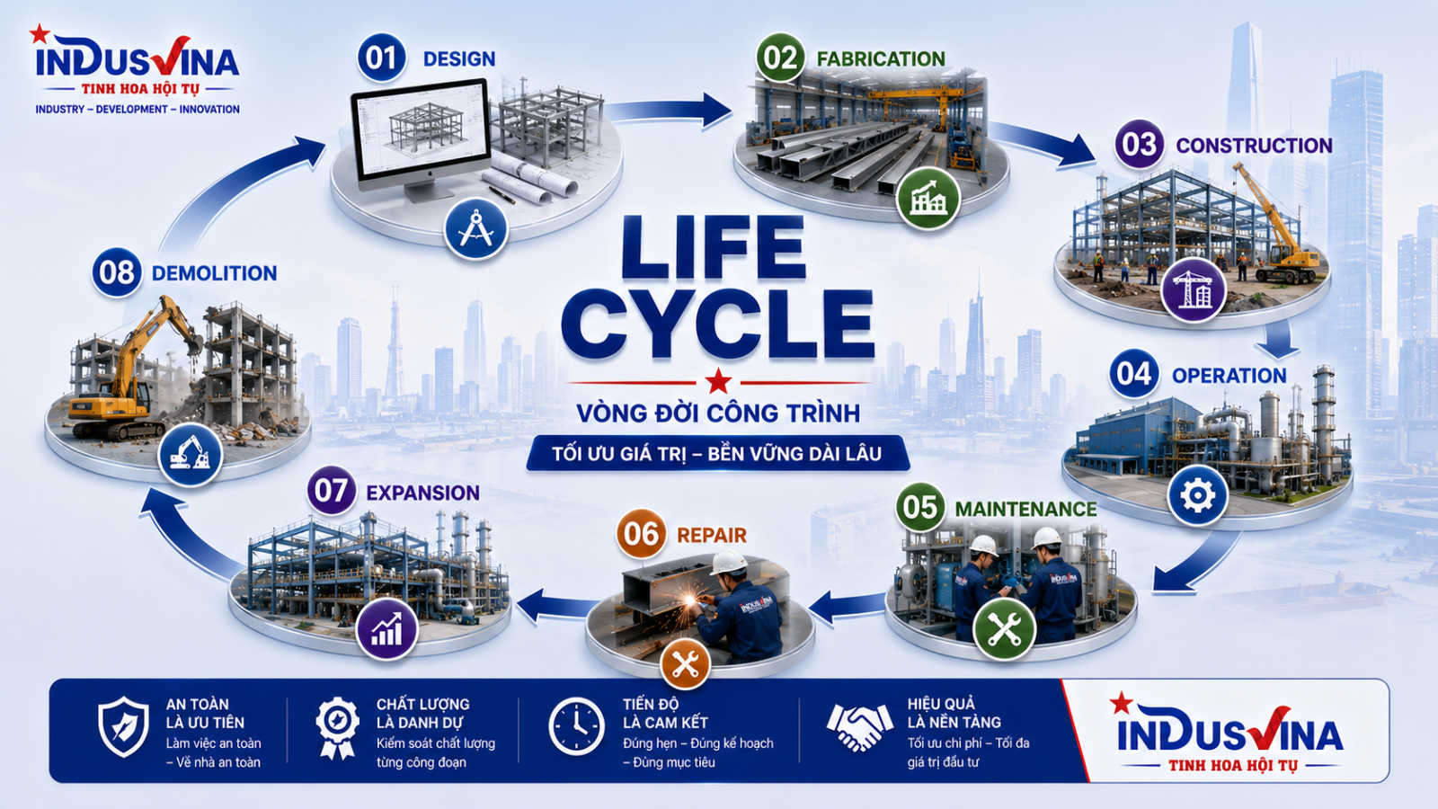
17. Factors affecting steel structure cost
Building geometry
Span, height, frame spacing, roof slope, number of floors and architectural complexity.
Design loads
Wind, seismic loading, roof loads, cranes, equipment, suspended loads and process loads.
Applicable standards
Standard system, tolerance requirements, weld inspection, NDT and quality documentation.
Surface-protection system
Surface preparation, number of coats, total DFT, galvanising and service environment.
Construction conditions
Site access, lifting equipment, working height, weather and work within operating facilities.
Schedule and logistics
Delivery sequence, shift work, oversized transport, unloading and accelerated completion requirements.
18. Why work with INDUSVINA?
INDUSVINA approaches projects through responsibility, engineering discipline, safety, quality and long-term life-cycle value.
System-based thinking
We connect design, production, construction, MEP, operation and maintenance instead of managing them as isolated tasks.
Control from the beginning
Standards, loads, interfaces, Hold Points and acceptance criteria are clarified before fabrication begins.
Transparent quality
Quality is demonstrated through records, checklists, inspection reports and traceability.
Support after handover
Inspection, repair, strengthening, modification and MRO maintenance support during operation.
19. Conclusion
- Correct design optimises materials and reduces interface conflicts.
- Correct shop drawings support accurate fabrication and erection.
- Correct fabrication reduces site rework.
- Correct erection ensures structural stability and safety.
- Correct QC/QA enables transparent acceptance and traceability.
- Correct maintenance extends service life and reduces life-cycle cost.
Related services and articles
FAQ – Steel Structures and Pre-Engineered Buildings
What types of projects are suitable for Pre-Engineered Buildings?
PEB systems are suitable for factories, warehouses, logistics centres, showrooms, parking buildings, sports facilities and other projects requiring large clear spans, rapid implementation and future expansion.
Are steel structures more durable than reinforced-concrete structures?
No general conclusion can be made based solely on the structural material. Durability depends on design, environment, corrosion protection, construction quality and maintenance. Each solution has its own suitable applications.


