


Technical Method Statement for Bored Pile Construction: Process, QC, QA, Safety and Acceptance Records
A small deviation at the pile toe, reinforcement cage or Tremie pipe can become a concealed foundation defect that is extremely difficult to repair. This guide helps engineers control the full life cycle of a bored pile—from design inputs, equipment and supporting fluid to construction, QA/QC, HSE, testing and final acceptance.
Explore this subject in the context of construction practice in Vietnam.
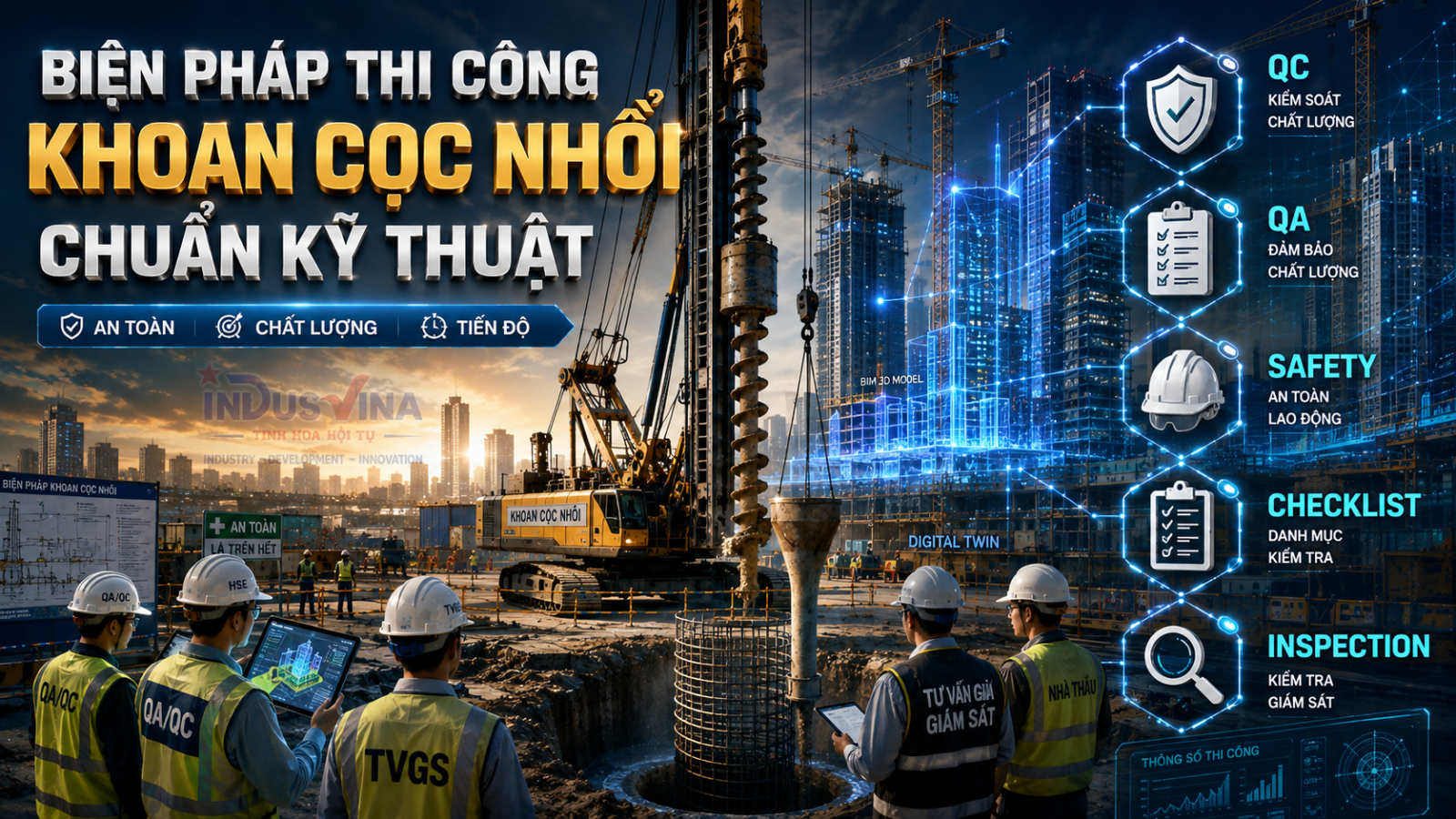
Table of Contents
- What is a bored pile and when should it be used?
- Pile configuration and required input data
- Comparison of deep-foundation solutions
- Drilling rigs, tools and equipment selection
- Ground conditions and geotechnical risks
- Bentonite and Polymer
- The 10-step construction process
- Reinforcement cage and CSL tubes
- Concrete placement by Tremie
- QA/QC workflow
- ITP, Hold Points and Checklists
- Tolerances and control criteria
- 20 common defects and failures
- PIT, CSL, PDA, static load and O-cell tests
- Occupational safety and environmental control
- Acceptance and as-built documentation
- BIM, Digital Twin and Drone applications
- FAQ and conclusion
1What is a bored pile and when should it be used?
A bored pile is a deep-foundation element formed by drilling or excavating a shaft in the ground, stabilising the bore with temporary casing or supporting fluid, lowering a reinforcement cage and placing concrete in situ using an approved method. Unlike precast piles that are driven or pressed into the ground, bored piles are constructed underground at the final location. Their quality therefore depends heavily on process control and verifiable construction records.
This solution is commonly used for high-rise buildings, hospitals, bridges, ports, industrial facilities, urban infrastructure and projects requiring high capacity, large pile diameter, significant founding depth or reduced vibration. However, bored piles are not automatically the optimum solution for every large project. Selection must be supported by structural loads, ground conditions, groundwater, available working space, adjacent assets, equipment capability, concrete logistics and quality-control capacity.
2Pile configuration and input data to be frozen before construction
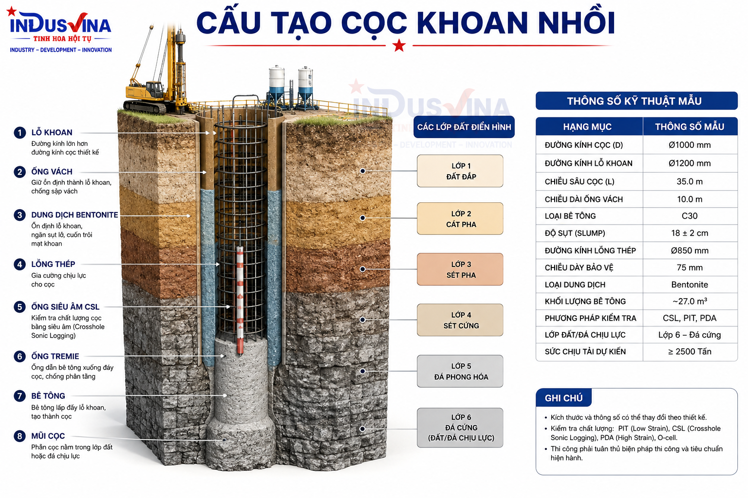
A completed bored pile comprises the concrete shaft, reinforcement cage, concrete cover, pile toe and pile head, together with testing provisions such as cross-hole sonic logging tubes where required. Temporary works also directly affect permanent quality: casing, supporting fluid, drilling tools, base-cleaning equipment and the Tremie system.
Design information
- Pile diameter, length and pile-head and pile-toe levels.
- Concrete strength class, reinforcement and concrete cover.
- Design capacity and serviceability limits.
- Testing requirements, test frequency and acceptance criteria.
Construction information
- Geotechnical investigation and groundwater conditions.
- Rig platform, access routes, slurry plant and cage assembly area.
- Capacity to supply concrete continuously.
- Proximity to existing structures and underground utilities.
3Comparison of bored piles, jacked piles, CFA piles and barrettes
| Solution | Main advantages | Main limitations | Typical applications |
|---|---|---|---|
| Bored pile | High capacity, flexible diameter and depth, relatively low vibration. | Highly dependent on bore stability, supporting fluid and Tremie control. | High-rise buildings, bridges and major industrial structures. |
| Jacked or pressed pile | Precast element quality can be checked before installation; process is relatively transparent. | Limited by segment length, jacking force, workspace and effects on adjacent structures. | Residential and medium-scale projects where jacking is feasible. |
| CFA pile | Continuous operation, limited open-hole exposure and good productivity under suitable conditions. | Requires control of extraction, concrete pressure and volume; depth and ground conditions may be restrictive. | Projects with suitable soils and high production requirements. |
| Barrette | Large section, high axial and bending resistance, good integration with diaphragm walls. | Complex specialist equipment, demanding control and higher cost. | Super-tall buildings and foundations with exceptionally high loads. |
This comparison must not be treated as a fixed selection rule. Each project requires an assessment of loads, geology, influence zones, logistics, programme and contractor capability.
4Drilling rigs, tools and equipment selection
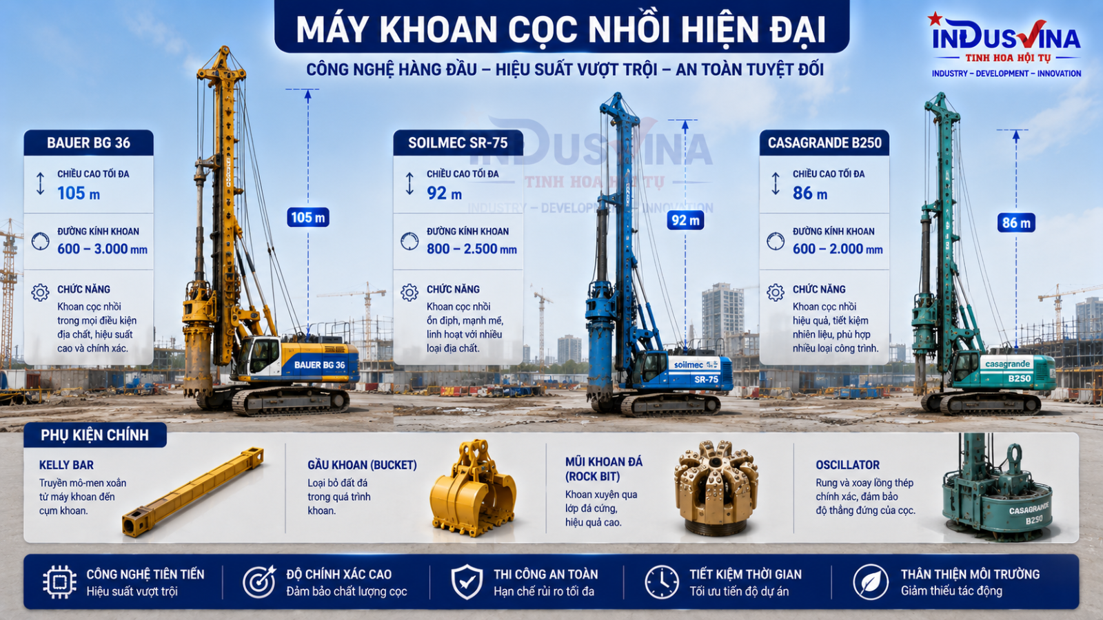
The drilling rig must be suitable for pile diameter, depth, required torque, Kelly bar configuration, platform capacity and available swing clearance. A manufacturer name does not replace verification of the actual machine configuration, operating loads, maintenance history, certification and tool condition.
Soft or loose soils
Use suitable buckets, maintain supporting-fluid head and control withdrawal speed to avoid excessive disturbance.
Gravel and cobbles
Provide breaking and retrieval tools together with contingency measures for fluid loss and tool entrapment.
Weathered rock and rock
Assess strength and discontinuities, select rock tools and monitor penetration rate and wear.
5Ground conditions determine drilling strategy and risk controls

A ground investigation describes conditions only at the investigation points. Between boreholes there may still be variable layers, sand lenses, soft pockets, boulders, voids, fractured rock or sloping rockhead. Each pile therefore requires a factual drilling log recording material recovered, penetration rate, tool changes, depth and abnormal events.
6Bentonite and Polymer supporting fluids
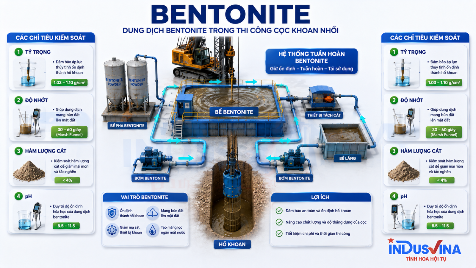
Supporting fluid provides hydrostatic pressure, limits soil and groundwater ingress and helps transport excavated material. Performance depends not only on the product name but also on mixing, hydration time, circulation, desanding, fluid level and compatibility with the ground.
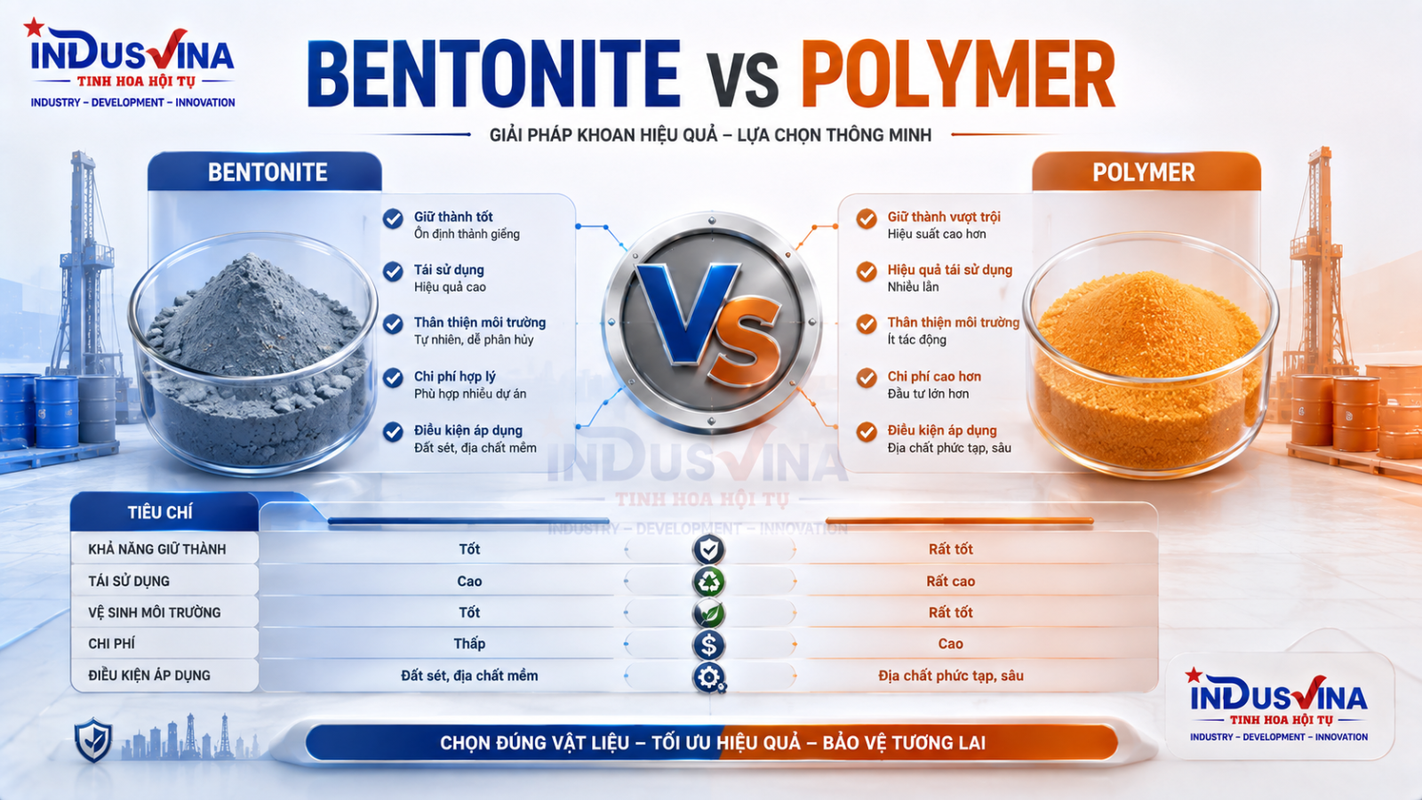
| Criterion | Bentonite | Polymer | Management requirement |
|---|---|---|---|
| Support mechanism | Filter cake and hydrostatic pressure. | Soil-particle interaction and solution stability depending on the proprietary system. | Demonstrate suitability for the actual ground. |
| Circulation | Normally requires tanks, pumps, desanding and treatment. | May be simpler but remains product- and process-dependent. | Do not mix systems indiscriminately; control batches and make-up water. |
| Environmental impact | Generates slurry requiring collection and disposal. | May reduce slurry volume but water and waste still require management. | No direct discharge to drainage channels or soil. |
| Testing | Density, viscosity, sand content, pH and project-specific parameters. | Viscosity, pH and properties specified by the supplier and approved procedure. | Test at the correct time and location using calibrated equipment. |
7The 10-step bored pile construction process
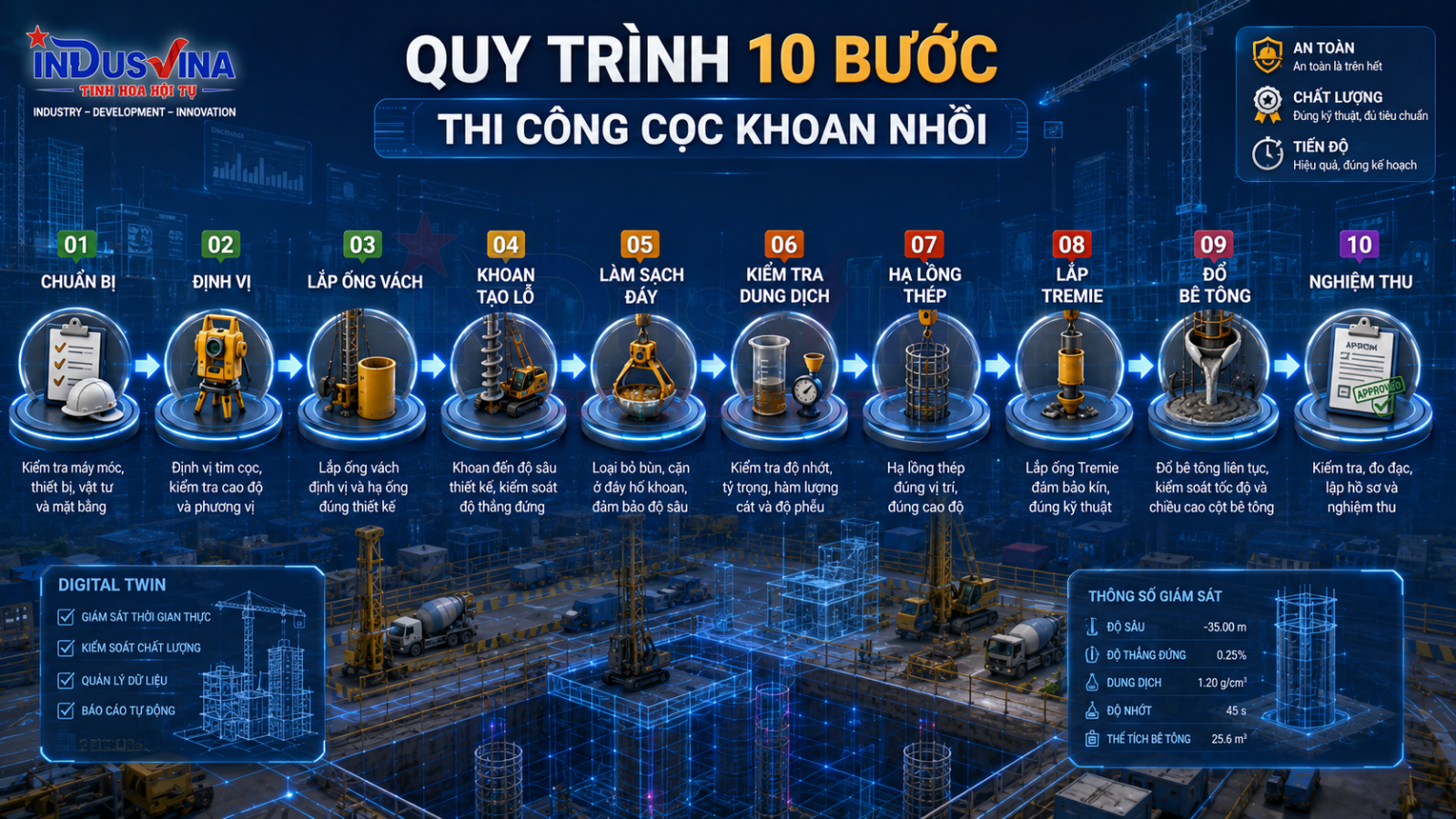
Step 1 – Prepare documents, platform and resources
Approve the method statement, ITP, drawings, HSE plan, concrete logistics, traffic route, slurry arrangement, standby equipment and inspection forms. Verify the rig platform for bearing capacity, level and drainage.
Step 2 – Set out the pile centre
Transfer coordinates and levels from approved control points using suitable survey instruments. Protect offset markers, perform an independent check and complete the survey record before casing installation.
Step 3 – Install temporary casing
The casing must be positioned to the approved centre and level, checked for verticality and embedded sufficiently to protect the bore entrance. The surrounding area must be stable and barricaded.
Step 4 – Drill the bore
Use approved tools and drilling parameters for each stratum. Maintain fluid head, monitor verticality and record depth, spoil and abnormal events. Avoid rapid withdrawal that may destabilise the bore or create suction.
Step 5 – Carry out initial base cleaning
Remove cuttings and settled material using a clean-out bucket, circulation or another approved method. Recheck the final depth after cleaning.
Step 6 – Inspect the bore and supporting fluid
Measure depth, verticality where required, base sediment and supporting-fluid properties. Progress only after compliance with drawings, project specifications and the approved ITP.
Step 7 – Lower the reinforcement cage
Inspect the cage before lifting. Lower it using the approved lifting points and splice sequence, then secure it at the correct level. Never force a cage past an obstruction.
Step 8 – Install Tremie and perform final cleaning
Check the watertightness of each joint, overall length, toe level and plug arrangement. Where waiting time causes renewed sedimentation or deterioration of fluid properties, repeat cleaning and testing.
Step 9 – Place concrete continuously
Check delivery tickets, elapsed time and workability. Continuously record concrete level, delivered volume and Tremie embedment. The Tremie toe must not be lifted out of the concrete mass.
Step 10 – Withdraw casing, trim the pile head and complete acceptance
Withdraw the casing in a controlled sequence to avoid lifting concrete or displacing the cage. Protect the pile head, perform specified tests, remove contaminated head concrete and compile the as-built records.
8Fabrication, inspection and installation of the reinforcement cage
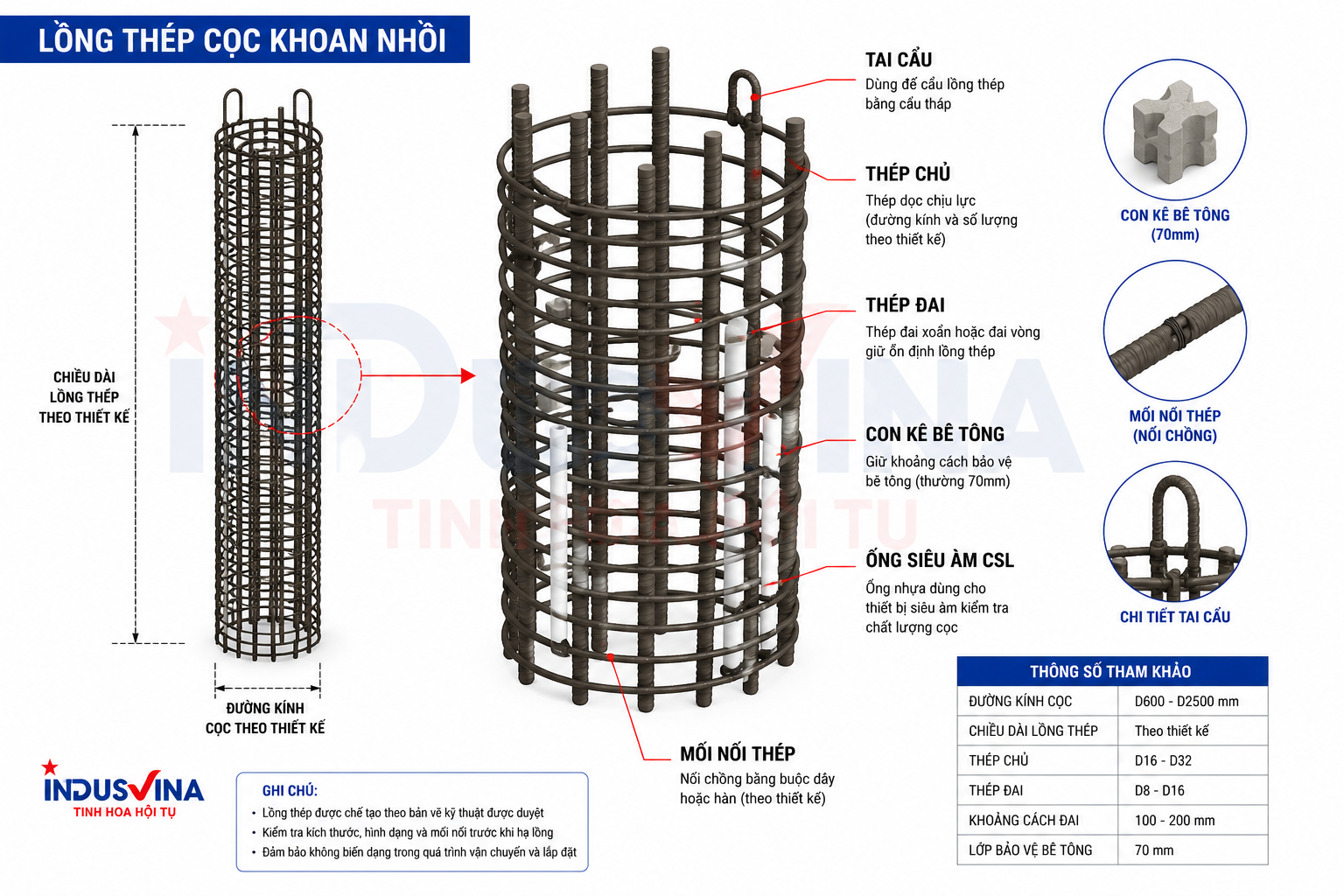
Geometric checks
- Diameter, individual segment lengths and total length.
- Number, diameter and spacing of main bars and links.
- Straightness, circularity, spacers and stiffening details.
Connections and lifting
- Splices comply with the approved drawings and procedure.
- Lifting lugs, lifting points and anti-deformation bracing.
- CSL tubes are sealed, securely fixed and protected at the ends.
9Concrete placement by Tremie
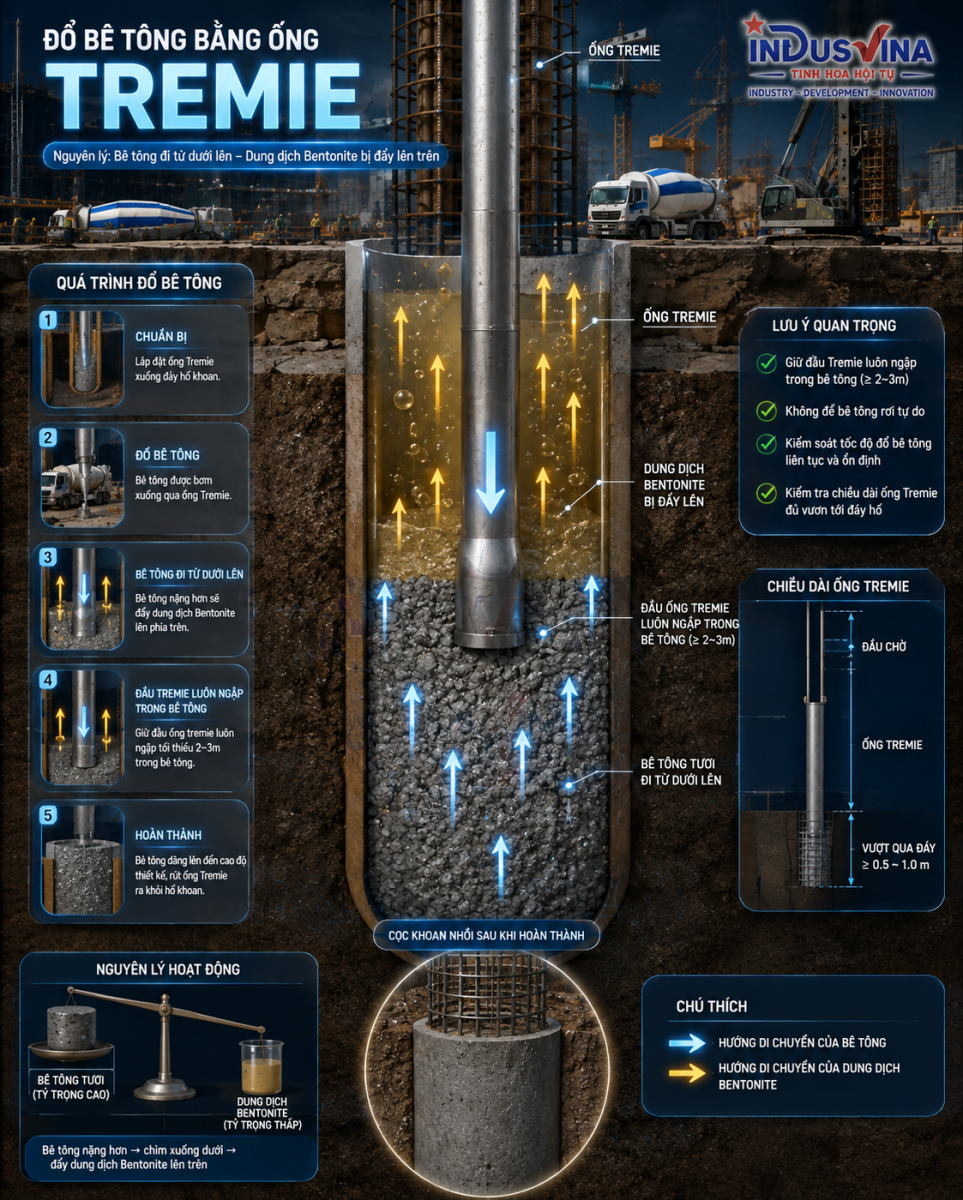
The Tremie provides a closed path for fresh concrete to reach the pile toe without free-falling through supporting fluid. Correct operation allows concrete to rise from the bottom and limits contamination. Major risks are leakage, blockage, interrupted supply, excessive pipe withdrawal and inaccurate level measurements.
| Item | Site control | Evidence |
|---|---|---|
| Tremie system | Clean, watertight, straight, correct total length and planned section removal. | Installation checklist and inspection record. |
| Concrete | Approved mix, suitable workability and continuous supply. | Delivery tickets, test results and specimens. |
| Embedment | Calculated from measured concrete level and Tremie toe level after each pipe removal. | Tremie log and volume-level chart. |
| Volume | Reconcile theoretical volume, truck volume and measured rise. | Pile Concrete Log. |
| Interruption | Record duration, cause, effect and authorised response. | Incident record or NCR where applicable. |
10QA/QC workflow: from approval to acceptance
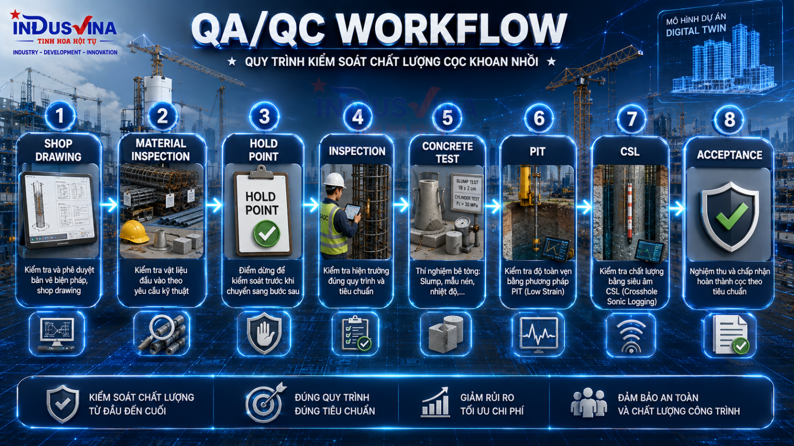
QA – Quality Assurance
- Approve the method, ITP, forms and personnel competence.
- Control documents, changes, measuring equipment and suppliers.
- Manage audits, NCRs, corrective action and lessons learned.
QC – Quality Control
- Inspect centre, level, fluid, base sediment and cage.
- Control concrete, Tremie, volume and records for each pile.
- Coordinate PIT, CSL, load tests and final acceptance.
11ITP, Hold Points and Checklists

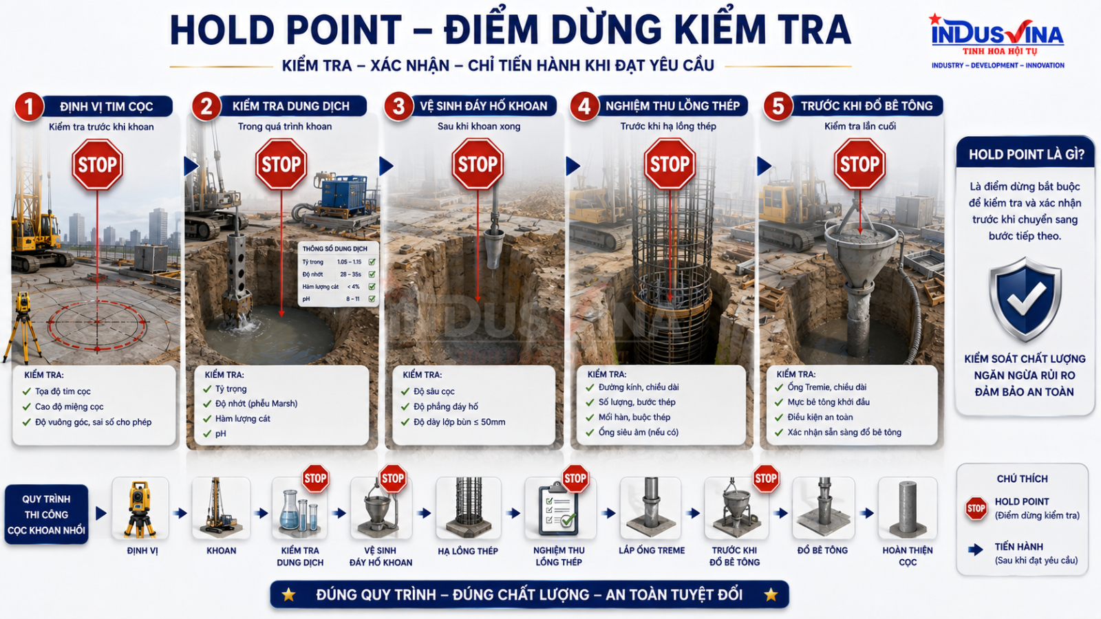
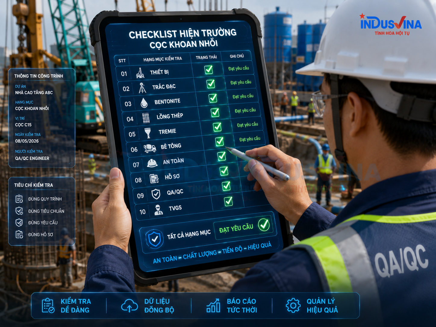
| Stage | Proposed control point | Point type | Record |
|---|---|---|---|
| Pre-construction | Method, ITP, equipment, survey control, platform and HSE. | Hold/Witness as defined by contract | Approvals and mobilisation checklist. |
| Setting out and casing | Centre, level, verticality and stability. | Witness | Survey record. |
| Completion of drilling | Depth, strata, bore base and supporting fluid. | Hold | Drilling log and fluid test report. |
| Reinforcement cage | Geometry, splices, spacers, CSL tubes and suspension level. | Hold | Cage inspection record. |
| Before concreting | Final cleaning, fluid, Tremie and concrete resources. | Hold | Pre-concrete checklist. |
| During concreting | Time, volume, level, embedment and sampling. | Surveillance | Concrete log, tickets and samples. |
| Post-construction | Pile head, testing, as-built records and NCR closure. | Review/Hold | Test reports and as-built documentation. |
12Tolerances and control criteria
Acceptance values must come from the drawings, technical specifications, applicable standards and project ITP. Limits must not be copied blindly from another project because diameter, depth, function, loading and contractual requirements may differ.
Geometry
Pile centre, level, diameter, depth, verticality and cage level.
Materials
Reinforcement, concrete, supporting fluid, spacers, CSL tubes and welding/splicing materials.
Process
Waiting time, base sediment, Tremie embedment, concrete volume and casing withdrawal sequence.
1320 common defects and control measures

| # | Defect | Typical cause or indication | Main control |
|---|---|---|---|
| 1 | Position deviation | Survey error, platform settlement or casing movement. | Independent survey check and platform monitoring. |
| 2 | Bore inclination | Rig out of vertical, inclined strata or unsuitable operation. | Check rig, casing and drilling method. |
| 3 | Bore collapse | Weak fluid, low fluid level or excessive open-hole time. | Maintain head, test fluid and control duration. |
| 4 | Fluid loss | Highly permeable layer, void or fractured ground. | Approved contingency materials and response plan. |
| 5 | Trapped tool | Obstruction, collapse or unsuitable tool. | Assess ground and implement a safe recovery procedure. |
| 6 | Insufficient depth | Incorrect level, rock obstruction or inadequate rig capability. | Verify datum, tooling and design direction. |
| 7 | Excessive base sediment | Inadequate cleaning, delay or wall instability. | Repeat cleaning and measurement before concreting. |
| 8 | Contaminated fluid | High sand content or poor circulation. | Desand, replace or condition the fluid. |
| 9 | Cage deformation | Insufficient stiffening or incorrect lifting points. | Engineer lifting points and stiffening members. |
| 10 | Cage obstruction | Inclined bore, distorted cage or wall collapse. | Do not force; investigate and rectify. |
| 11 | Cage uplift | Concrete buoyancy and inadequate restraint. | Monitor cage level and provide secure restraint. |
| 12 | Blocked or leaking CSL tube | Open joints or unprotected tube ends. | Leak-test, secure and cap tubes correctly. |
| 13 | Tremie blockage | Dirty pipe, unsuitable concrete or defective plug. | Clean, inspect and prepare a contingency system. |
| 14 | Loss of Tremie embedment | Incorrect level calculation or excessive pipe withdrawal. | Measure level and update the log after every removal. |
| 15 | Interrupted concrete supply | Insufficient trucks, traffic delay or batching-plant failure. | Supply plan and standby plant or trucks. |
| 16 | Concrete segregation | Unsuitable mix, free fall or fluid contamination. | Control workability and Tremie operation. |
| 17 | Necking | Collapse, soil pressure, interruption or concrete loss. | Control the bore, volume and integrity testing. |
| 18 | Insufficient concrete volume | Incorrect records, loss or incorrect level. | Continuously reconcile trucks, volume and measured rise. |
| 19 | Weak pile head | Floating contamination, polluted concrete or inadequate overcast. | Provide specified overcast and trim to sound concrete. |
| 20 | Untraceable records | Incomplete logs, conflicting data or unidentified photographs. | Use consistent pile IDs, digital forms and end-of-shift review. |
14PIT, CSL, PDA, static load and O-cell tests

| Method | Main purpose | Conditions and limitations |
|---|---|---|
| PIT | Screen pile continuity and identify unusual wave reflections. | Requires properly prepared pile head and specialist interpretation; it does not replace a load test. |
| CSL | Assess concrete quality between access tubes. | Depends on tube layout and condition and covers only the scanned zones. |
| PDA | Analyse dynamic response, resistance and stresses under suitable test conditions. | Requires an impact source and appropriate analytical model. |
| Static load test | Measure load-displacement behaviour under the specified test arrangement. | Requires a reaction system, calibrated instrumentation, loading sequence and significant time. |
| O-cell | Conduct bidirectional load testing using a cell installed within the pile. | Must be designed and installed in advance; results require specialist conversion and interpretation. |
The testing plan must be established through design and contract requirements: test type, frequency, timing, acceptance criteria, testing organisation, response to anomalous results and approval responsibility.
15Occupational safety and environmental protection
Bored piling combines major hazards: heavy rigs on working platforms, rotating machinery, suspended cages and Tremie pipes, deep open bores, slippery slurry, concrete trucks, temporary power, night work and schedule pressure.
Critical HSE controls
- Rigid barriers around open bores and the rig swing zone.
- Lift plans, appointed lifting supervisors and exclusion zones.
- Inspection of the platform, ropes, hooks, locks and operating limits.
- Lighting, walkways, slip prevention and traffic management.
- Stop Work Authority when conditions differ from the approved method.
Environmental controls
- Contained slurry tanks and transfer lines.
- Collection of spoil, slurry and wash water.
- No direct discharge to drainage systems.
- Wheel washing, covered transport and road-cleaning controls.
- Control of noise, vibration and permitted working hours.
16Acceptance and as-built documentation
Approved documents
- Drawings, method statement, ITP, HSE and environmental plan.
- Competence of personnel, equipment and testing organisation.
- Materials, concrete mix, supporting fluid and welding/splicing procedures.
Records for each pile
- Setting-out and casing inspection.
- Drilling log, strata, depth, supporting fluid and base sediment.
- Cage, Tremie and pre-concrete inspections.
- Concrete log, truck tickets, specimens and casing-withdrawal record.
Post-construction records
- Concrete results and pile test reports.
- NCRs, repairs and closure evidence.
- As-built coordinates, levels and pile schedule.
- Stage and final acceptance records.
Consistency review
- Consistent pile identification across every form.
- No conflict in dates, times and measured values.
- Photographs include location and time identification.
- Signatures are by authorised parties at the correct Hold Point.
17BIM, Digital Twin and Drone applications
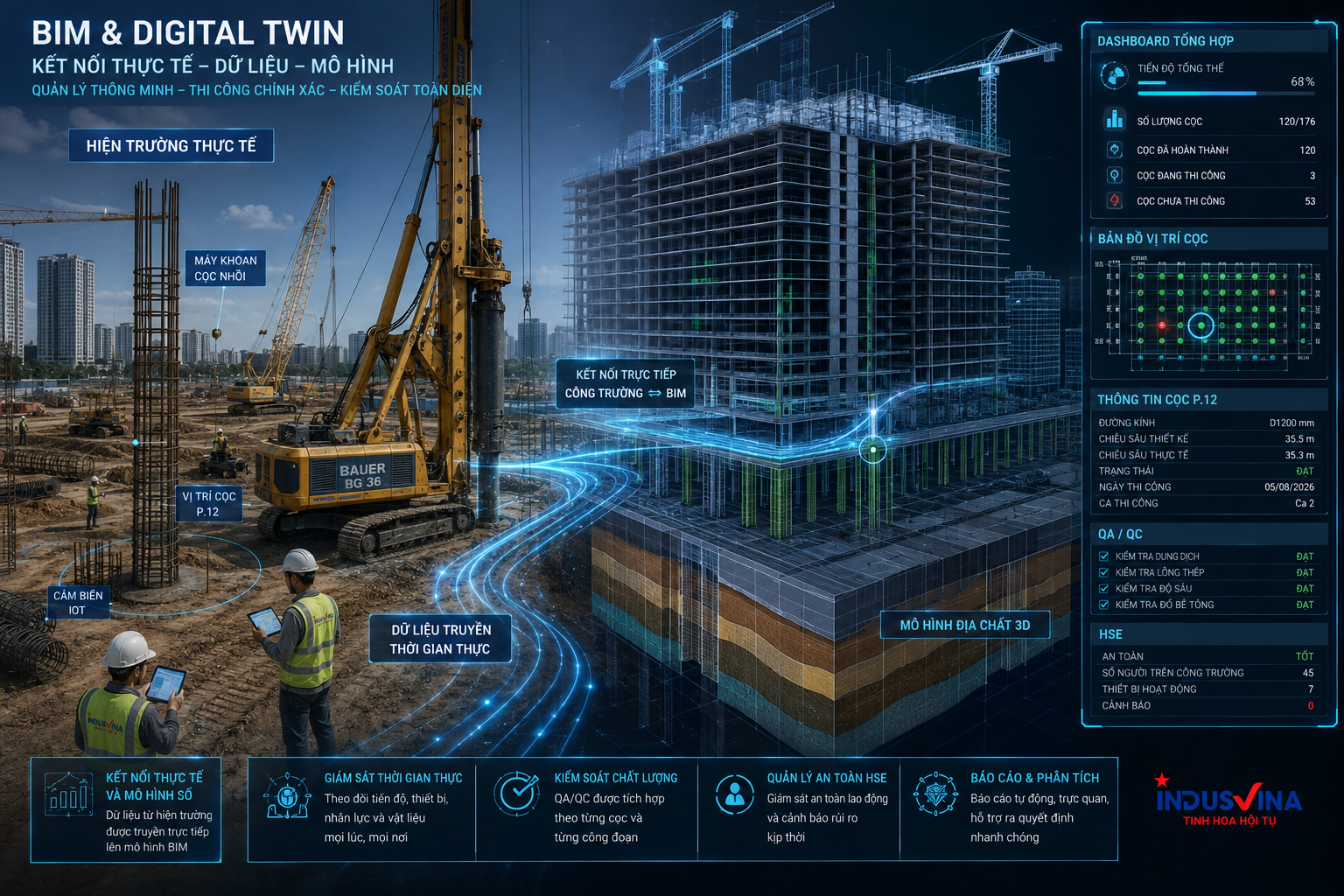

BIM
Manage coordinates, pile IDs, clashes, levels and object-linked records.
Digital Twin
Connect actual progress, rig data, concrete, tests and alerts.
Drone and AI
Record site logistics, traffic routes, exclusion zones, storage and changes over time.
Technology adds value only when data is reliable, coding is consistent, thresholds are defined and each alert has a responsible recipient and required action. An attractive dashboard with incomplete data and no accountable owner will not improve quality.
Sample case study: controlling a large-diameter bored pile
For a large-diameter, deep pile, organise documentation as “one pile—one complete data set”: setting-out record, drilling log, strata profile, supporting-fluid results, base sediment, reinforcement cage, Tremie data, every concrete truck, concrete level, cumulative volume, interruption time, specimens and post-construction testing.
Before concreting, conduct a focused coordination meeting to freeze the concrete source, truck route, standby plant, level-measurement responsibility, logging responsibility, authority to shorten Tremie, communication signals, lighting, backup power and response to delayed trucks or pipe blockage. This converts a variable operation into a prepared sequence of decisions.
Related articles and services
FAQ – Frequently Asked Questions
What are the most important controls in bored pile construction?
The three major groups are bore stability, base cleaning and uninterrupted Tremie concreting. All three must operate within an effective QA/QC system and approved Hold Points.
When should Bentonite or Polymer be used?
Selection depends on the ground, water chemistry, circulation equipment, environmental requirements, product instructions and trial evidence. The choice must not be based on unit cost alone.
Why may the bore base need to be cleaned twice?
After drilling and during cage installation, cuttings may settle again or additional material may enter the bore. The exact process must follow the approved method and actual inspection results.
How much Tremie embedment is required?
The applicable value must follow project specifications, standards and the approved method. The essential requirement is to measure concrete level, update the calculation after every pipe removal and prevent the Tremie toe from leaving the concrete mass.
Can PIT replace a pile load test?
No. PIT primarily screens pile continuity from reflected-wave response. Load-bearing behaviour must be assessed by a test method suitable for the design objective.
Does CSL inspect the entire pile?
CSL assesses the concrete zone between installed access tubes. Coverage and result quality depend on tube arrangement, tube condition, spacing and test procedure.
When must work be stopped?
Stop when conditions differ from the approved method, the platform becomes unstable, the bore behaves abnormally, supporting fluid or base sediment fails, the cage or Tremie is defective, continuous concrete supply is not assured or an uncontrolled HSE risk is present.
What is the most important record for an individual pile?
No single form is sufficient. A complete traceable record is needed from setting out, drilling, supporting fluid and base cleaning through cage, Tremie, concrete, testing and as-built acceptance.
Conclusion
A sound bored pile is never the result of luck. It results from reliable input data, suitable plant and tools, competent people, respected Hold Points, uninterrupted concrete control and traceable documentation.
For deep foundations, the work that becomes invisible after completion is the work that determines long-term performance. The objective of a method statement is therefore not merely approval. It must ensure that every party knows what to inspect, where to stop, who may decide and what evidence proves compliance.
Connect with INDUSVINA
Discuss method statements, ITPs, Hold Points, QA/QC checklists, HSE, acceptance documentation, construction, MEP and MRO requirements for your project.


